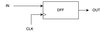
In this blog post we will see a beginners guide on how to write DFF (Data Flip Flop) in Verilog. Verilog is a Hardware Description Language (HDL) which is used to describe the functionality of a hardware (electronic systems) in a programming language. There are many resources online if you want to learn more about Verilog.
DISCLAIMER
We will be only looking at the Behavior modelling and not Gate level modelling. Since behavior modelling is easier to understand and read.
What is a Data Flip Flop?
Flip-Flops are part of the family of sequential logic gates because flip-flops deals with clock signals (the heartbeat of sequential logic gates).
To put it simply, a data flip flop is a storage element to store a single bit of data. Since it can only store a single bit, its states will be either 1 or 0. We will see how it stores the data in detail in later part of this post to understand more about it.

Now that we have a decent understanding of what a data flip flop is and what it is used for, let’s look at the implementation.
Implementing DFF
module DFF(
   input D, CLK,
   output reg Q
);
   always @(posedge CLK) begin
       Q <= D;
   end
endmodule
We have declared a module in Verilog named DFF, which stands for Data Flip Flop. This module takes in 3 things.
- D - which stands for Data as an input
- CLK - which stands for Clock Signal as an input
- Q - which is our output
In the body of the module, we have a procedural block called always block. In Verilog, always block is used to describe behaviour that occur continuously or repeatedly based on certain conditions. In our case, we have posedge CLK. posedge is short for positive edge, and posedge CLK means positive edge of the clock. Positive edge is nothing but, when the clock signal goes from 0 to 1. So whenever the value of *CLK* goes from 0 to 1, the always block gets executed.
Inside the always block we have, Q <= D which means we are assigning the value of D to Q. If suppose, D = 1 then the value of Q becomes 1.
<= means non-blocking assignment. I’m not gonna go into the details of it. You can google what’s the difference between blocking and non-blocking assignment in Verilog.
We have successfully implemented a Data Flip Flop. Now let’s test it.
Testing our DFF
Now that we have implemented our DFF, we have to test it to make sure its behaving as expected.
Question: What’s the behavior that we want to test?
Answer: At the positive edge of the clock, whatever value(usually binary) is passed as input (D) should be the output. During other times, the output will be the previous output.
Let’s write our testbench:
module dff_tb;
   reg D = 0;
   reg CLK = 0;
   wire Q;

   DFF dff(
       .D(D),
       .CLK(CLK),
       .Q(Q)
   );

   always #5 CLK <= ~CLK;

   initial begin
       #10 D = 1;
       #10 D = 0;
       #10 D = 1;

       #10 $finish;
   end

   initial $monitor("[Time=%0t] D = %0b CLK = %0b Q = %0b", $time, D, CLK, Q);
endmodule
In our testbench, we have defined two variables (D and CLK) which will be the inputs of the data flip flop and we have declared one variable (Q) which will be the output of our flip flop.
Next we have initialized our data flip flop (DFF) by passing in our variables.
Now comes the meaty part. We have three procedural blocks,
- always
- initial
The always block toggles the value of CLK every 5 seconds.
In the first initial block, we are assigning values to the D register.
- At time unit
10ns, the value ofDis1 - At time unit
20ns, the value ofDis0 - At time unit
30ns, the value ofDis1
In the second initial block, we have a system task called monitor. It continuously tracks and displays the values of specified signals whenever there is a change in any of them.
When we run the testbench, we will get the following output:
[Time:                    0], D=0, CLK=0, Q=x
[Time:                    5], D=0, CLK=1, Q=0
[Time:                   10], D=1, CLK=0, Q=0
[Time:                   15], D=1, CLK=1, Q=1
[Time:                   20], D=0, CLK=0, Q=1
[Time:                   25], D=0, CLK=1, Q=0
[Time:                   30], D=1, CLK=0, Q=0
[Time:                   35], D=1, CLK=1, Q=1
dff_tb.v:21: $finish called at 40 (1s)
[Time:                   40], D=1, CLK=0, Q=1
Whenever the value of CLK is 1, the value of Q is whatever the value of D. And other times (value of CLK=0), the value of Q is the previous value of D.
Voila 🎉 we have successfully implemented and tested our Data Flip Flop. To take it further, you can use this to build Registers.