This post is about how to write a 4-bit Counter with synchronous reset in Verilog. But what do I mean by Counter? A Counter counts from 0 to n, where n > 0. Usually we count in decimals like 0, 1, 2, 3, 4, 5...n. But computers don’t count like that, they count in binary as we all know.
The 4-bit Counter counts from 0 to 15. But why only 15? because that’s the highest value of the number that we can represent in 4-bits (0000 = 0, 1111 = 15).
Let’s count from 0 to 15 in Binary:
0000  = 0
0001 = 1
0010 = 2
0011 = 3
0100 = 4
0101 = 5
0110 = 6
0111 = 7
1000 = 8
1001 = 9
1010 = 10
1011 = 11
1100 = 12
1101 = 13
1110 = 14
1111 = 15
Now let’s first look at how to write a 4-bit Counter in Verilog without Synchronous reset.
// counter.v
module Counter4Bit(
   input clk,
   output reg [3:0] count // 4-bit to hold value till 1111 (15 in Decimal)
);
   always @(posedge clk) begin
       count <= count + 1;
   end
endmodule
module counter_tb;
   reg clk;
   wire [3:0] count;

   Counter4Bit counter(
       .clk(clk), .count(count)
   );

   always #1 clk = ~clk;

   initial begin
       clk = 0; // initial value of clk at 0ns time unit.

       #100 $finish; // stop the simulation after 100ns time unit
   end
endmodule
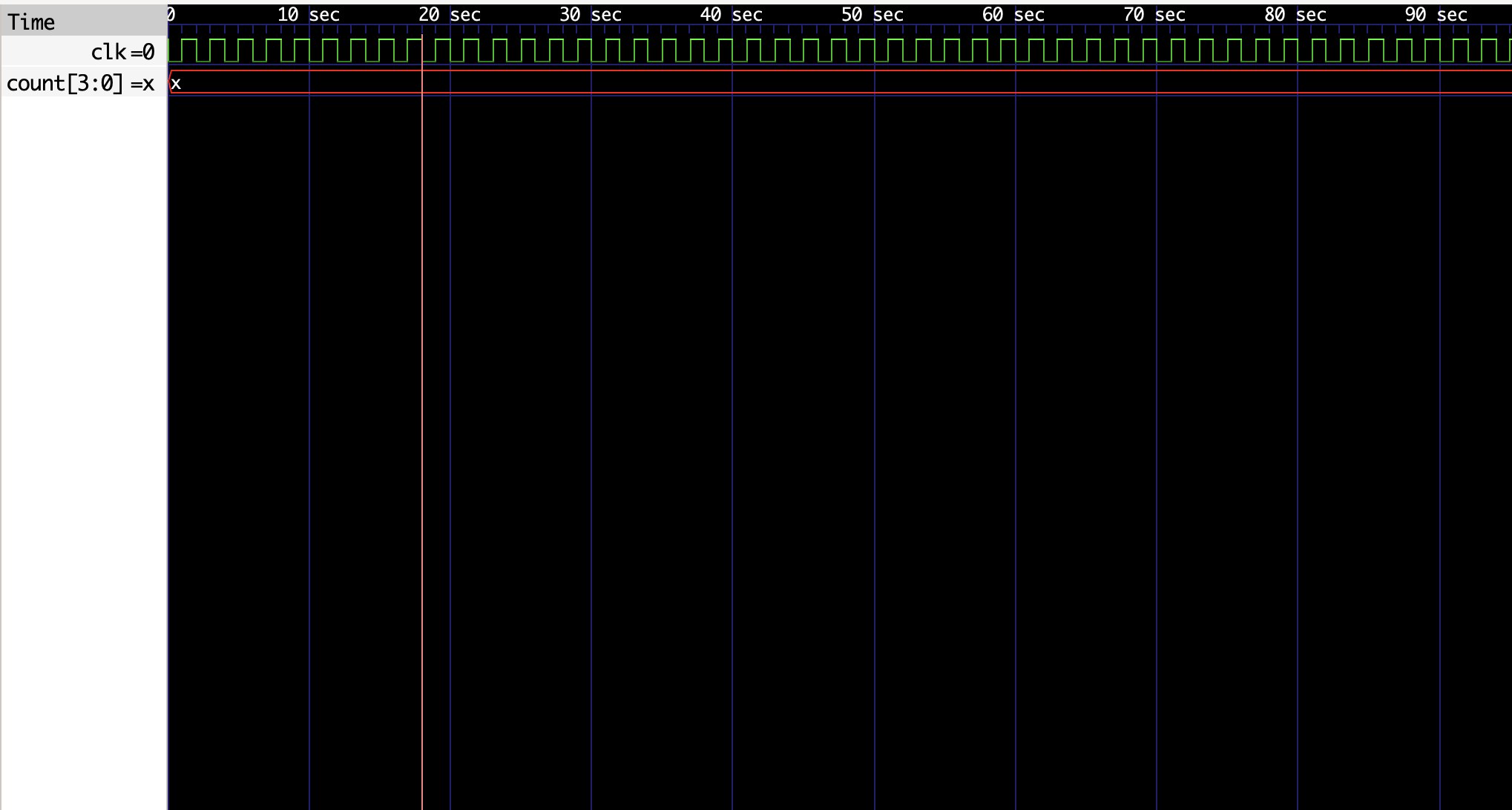
If we run the above design code along with the testbench, we can see that the output of count will always be x. But what is x? In Verilog, x represents unknown or undefined value.
The reason is because:
- At time unit
0ns, the value ofclkis0and the value ofcountisxwhich is the initial value. - At time unit
1ns, the value ofclkis1and the value ofcountis stillx. This is because we can’t add anything with unknown or undefined value. That is why at the positive edge of theclk,count = x + 1which results tox.
So, how can we fix this? We need to provide a way to set the value of count to 0 when the clk (clock) goes from negative edge to positive edge (0 to 1). This is where reset comes in. Let’s take a look at the slightly modified version of the design code and testbench.
// design code
module Counter4Bit(
   input clk, reset,
   output reg [3:0] count
);
   always @(posedge clk) begin
       if (reset) begin
           count <= 0;
       end else begin
           count <= count + 1;
       end
   end
endmodule
// testbench
module counter_tb;
   reg clk, reset;
   wire [3:0] count;

   Counter4Bit counter(
       .clk(clk),
       .reset(reset),
       .count(count)
   );

   // for every 2ns time unit, clk goes from 0 to 1 to 0
   always #1 clk = ~clk;

   initial begin
       clk = 0; reset = 0; // set initial values at 0ns time unit
       #1 reset=1; // set the initial value of count to 0
       #1 reset=0; // increment count

       #30 $finish; // stop the simulation after 33ns time unit
   end
endmodule
Let’s breakdown the above design code and testbench:
- We’ve added a
resetwire as output inCounter4Bitmodule. Whenever the value ofresetis1it setscountto0. - In the testbench, we’ve set the initial value of
resetto0at0nstime unit. - At
1nstime unit, we are makingresetas1, this make sure that the initial value ofcountis set to0. Also this happens when the value ofclkis1. - At
2nstime unit, we are makingresetas0to start incrementing the value ofcountby 1.
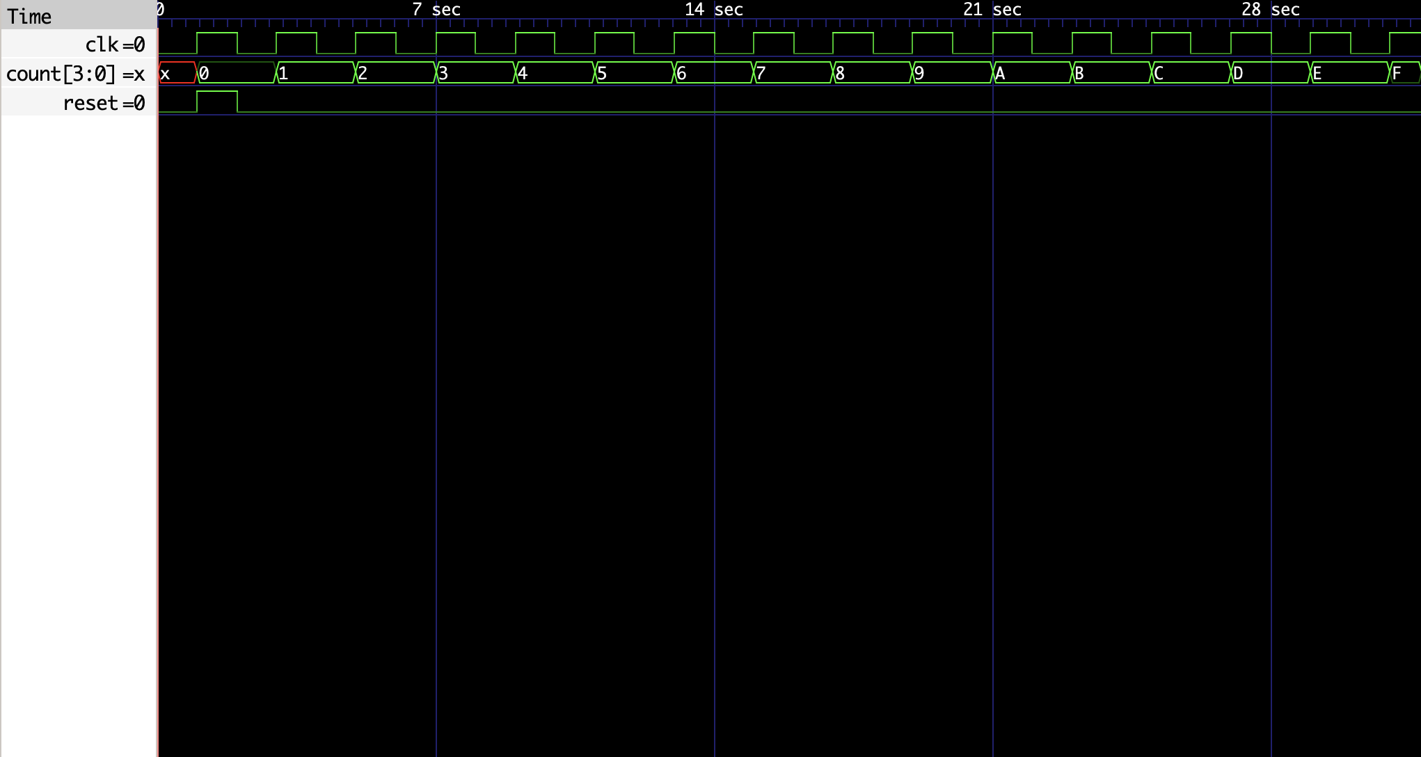
When we run the above design code and testbench:
- At time unit
0ns, clk=0, reset=0 and count=xxxx - At time unit
1ns, clk=1, reset=1 and count=0 - At time unit
2ns, clk=0, reset=0 and count=0 - At time unit
3ns, clk=1, reset=0 and count=1 - At time unit
4ns, clk=0, reset=0 and count=1 - At time unit
5ns, clk=1, reset=0 and count=10 - At time unit
6ns, clk=0, reset=0 and count=10 - ….
- At time unit
32ns, clk=0, reset=0 and count=1111
This is a brief description about how to write a 4-bit Counter with Synchronous reset in Verilog. The reference code can be found here.